
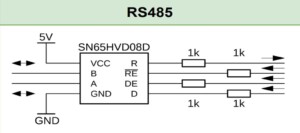
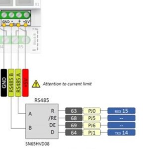
Nuestros PLCs de Controllino en sus modelos MAXI y MEGA tiene la característica de poder comunicarse usando el protocolo ModbusRTU a través del puerto RS485 (interfaz SN65HVD08) integrado en ellos, la cual cuenta con distintos seriales para la transmisión de datos como digital, conexión en línea o diferencial. Al conectarse a las terminales atornillables las señales pueden llegar hasta 32 suscriptores en un rango de 1,200 metros, esto gracias al driver del módulo RS845 de Controllino conectado al UART3 (TxD3 / RxD3) del microchip ATMEGA2560.
Controllino ofrece un diagrama de conexiones para el PLC de Controllino MAXI en archivo pdf, haciendo la configuración de conexión mediante Modbus más sencilla, en este blog le enseñaremos a configurar y probar la interfaz RS485 en sus equipos (Nota: se debe seleccionar la librería correcta buscando en la dirección del menú de Arduino IDE Tools->Board->Controllino MINI/MAXI/MEGA, si no encuentra el archivo deseado puede usar la esta liga para descargarlo, ya que la necesita antes de cargar el código al PLC).
En este caso lo que va a necesitar para la configuración son 2 equipos PLC de Controllino MAXI y/o MEGA, una fuente de alimentación de 12/24 VCD (la cual deberá configurar para que el voltaje que reciban los PLC no exceda los 5 Volts, o se corre el riesgo de dañar permanentemente los equipos).
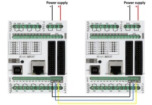
Las imágenes de arriba muestran el cableado y conexión de los PLCs, antes de realizar esto se debe cargar este código al PLC que fungirá como emisor:
#include <SPI.h>
#include <Controllino.h> /* Usage of CONTROLLINO library allows you to use CONTROLLINO_xx aliases in your sketch. */
void TestRS485 (int mode)
{
DDRJ = DDRJ | B01100000;
PORTJ = PORTJ & B10011111;
/*pinMode(CONTROLLINO_RS485_TX, OUTPUT);
pinMode(CONTROLLINO_RS485_RX, INPUT);
pinMode(CONTROLLINO_RS485_RE, OUTPUT);
pinMode(CONTROLLINO_RS485_DE, OUTPUT);*/
switch (mode)
{
case 0:
PORTJ = PORTJ & B10011111;
PORTJ = PORTJ | B01000000;
/*digitalWrite (CONTROLLINO_RS485_RE, HIGH);
digitalWrite (CONTROLLINO_RS485_DE, HIGH);*/
delay (10);
Serial.println (“Sending test message, expected to return;”);
Serial3.print(“UUUUU Controllino RS485 test Message.UUUUU”);
break;
case 1:
PORTJ = PORTJ & B10011111;
PORTJ = PORTJ | B01100000;
/*digitalWrite (CONTROLLINO_RS485_RE, LOW);
digitalWrite (CONTROLLINO_RS485_DE, HIGH);*/
delay (10);
Serial.println (“Sending test message, not expected to return;”);
Serial3.print(“UUUUU Controllino RS485 test Message.UUUUU”);
break;
case 2:
PORTJ = PORTJ & B10011111;
PORTJ = PORTJ | B00100000;
/* digitalWrite (CONTROLLINO_RS485_RE, HIGH);
digitalWrite (CONTROLLINO_RS485_DE, LOW);*/
delay (10);
Serial.println (“Sending test message, not expected to be sended;”);
Serial3.print(“UUUUU Controllino RS485 test Message.UUUUU”);
break;
default:
Serial.println(“Wrong mode!”);
return;
}
}
/* This function enters a loop and waits for any incoming data on serial 3.*/
void RecieveRS485()
{
Serial.println(“Recieving RS485.”);
while(true)
{
if (Serial3.available())
{
// print the new byte:
Serial.print((char)Serial3.read());
}
}
}
void setup() {
/* Here we initialize USB serial at 9600 baudrate for reporting */
Serial.begin(9600);
/* Here we initialize RS485 serial at 9600 baudrate for communication */
Serial3.begin(9600);
/* This will initialize Controllino RS485 pins */
Controllino_RS485Init();
}
void loop() {
/* Use only one of the two functions, either send or receive */
// ReceiveRS485();
/* Sends test. 2 seconds apart sending messages with 3 types of different settings.
Check the function comment for more information */
TestRS485(0);
delay(2000);
TestRS485(1);
delay(2000);
TestRS485(2);
delay(2000);
}
Una vez hecho esto, no olvide cargar este código al PLC que fungirá como receptor:
#include <SPI.h>
#include <Controllino.h> /* Usage of CONTROLLINO library allows you to use CONTROLLINO_xx aliases in your sketch. */
void TestRS485 (int mode)
{
DDRJ = DDRJ | B01100000;
PORTJ = PORTJ & B10011111;
/*pinMode(CONTROLLINO_RS485_TX, OUTPUT);
pinMode(CONTROLLINO_RS485_RX, INPUT);
pinMode(CONTROLLINO_RS485_RE, OUTPUT);
pinMode(CONTROLLINO_RS485_DE, OUTPUT);*/
switch (mode)
{
case 0:
PORTJ = PORTJ & B10011111;
PORTJ = PORTJ | B01000000;
/*digitalWrite (CONTROLLINO_RS485_RE, HIGH);
digitalWrite (CONTROLLINO_RS485_DE, HIGH);*/
delay (10);
Serial.println (“Sending test message, expected to return;”);
Serial3.print(“UUUUU Controllino RS485 test Message.UUUUU”);
break;
case 1:
PORTJ = PORTJ & B10011111;
PORTJ = PORTJ | B01100000;
/*digitalWrite (CONTROLLINO_RS485_RE, LOW);
digitalWrite (CONTROLLINO_RS485_DE, HIGH);*/
delay (10);
Serial.println (“Sending test message, not expected to return;”);
Serial3.print(“UUUUU Controllino RS485 test Message.UUUUU”);
break;
case 2:
PORTJ = PORTJ & B10011111;
PORTJ = PORTJ | B00100000;
/* digitalWrite (CONTROLLINO_RS485_RE, HIGH);
digitalWrite (CONTROLLINO_RS485_DE, LOW);*/
delay (10);
Serial.println (“Sending test message, not expected to be sended;”);
Serial3.print(“UUUUU Controllino RS485 test Message.UUUUU”);
break;
default:
Serial.println(“Wrong mode!”);
return;
}
}
/* This function enters a loop and waits for any incoming data on serial 3.*/
void ReceiveRS485()
{
Serial.println(“Receiving RS485.”);
while(true)
{
if (Serial3.available())
{
// print the new byte:
Serial.print((char)Serial3.read());
}
}
}
void setup() {
/* Here we initialize USB serial at 9600 baudrate for reporting */
Serial.begin(9600);
/* Here we initialize RS485 serial at 9600 baudrate for communication */
Serial3.begin(9600);
/* This will initialize Controllino RS485 pins */
Controllino_RS485Init();
}
void loop() {
/* Use only one of the two functions, either send or receive */
ReceiveRS485();
/* Sends test. 2 seconds apart sending messages with 3 types of different settings.
Check the function comment for more information */
// TestRS485(0);
// delay(2000);
// TestRS485(1);
// delay(2000);
// TestRS485(2);
// delay(2000);
}
- Usar ModbusRTU
El siguiente paso una vez que salieron positivas las pruebas en los PLCs es comunicar los dispositivos vía RS485 con ayuda del protocolo ModbusRTU. Para eso usaremos el sistema de enlace conocido de Maestro y Esclavo. La función del Maestro será la lectura periódica de los registros de 16 bits del Esclavo e impresión del estatus actual al serial de debug, luego escribirá y alternará los registros:
0 – analog CONTROLLINO_A0 value (0 – 1024)
1 – digital CONTROLLINO_D0 value (0/1)
2 – Modbus messages received
3 – Modbus messages transmitted
4 – relay CONTROLLINO_R0 (0/1)
5 – relay CONTROLLINO_R1 (0/1)
6 – relay CONTROLLINO_R2 (0/1)
7 – relay CONTROLLINO_R3 (0/1)
Para lograr la conexión necesitamos además al segundo PLC Controllino como Esclavo, recordando cargar antes las librerías de Modbus Maestro-Esclavo de este enlace, esto nos ayudará a modificar los parámetros de los puertos para los pines de control DE (PIN6) y RE (PIN5).
El código para el equipo ModbusRTU Maestro es el siguiente:
#include <Controllino.h> /* Usage of CONTROLLINO library allows you to use CONTROLLINO_xx aliases in your sketch. */
#include “ModbusRtu.h” /* Usage of ModBusRtu library allows you to implement the Modbus RTU protocol in your sketch. */
// This MACRO defines the Modbus master address.
// For any Modbus slave devices are reserved addresses in the range from 1 to 247.
// Important note only address 0 is reserved for a Modbus master device!
#define MasterModbusAdd 0
#define SlaveModbusAdd 1
// This MACRO defines the number of the comport that is used for RS 485 interface.
// For MAXI and MEGA RS485 is reserved UART Serial3.
#define RS485Serial 3
// The object ControllinoModbuSlave of the class Modbus is initialized with three parameters.
// The first parameter specifies the address of the Modbus slave device.
// The second parameter specifies the type of the interface used for communication between devices – in this sketch – RS485.
// The third parameter can be any number. During the initialization of the object this parameter has no effect.
Modbus ControllinoModbusMaster(MasterModbusAdd, RS485Serial, 0);
// This uint16 array specified internal registers in the Modbus slave device.
// Each Modbus device has particular internal registers that are available for the Modbus master.
// In this example sketch internal registers are defined as follows:
// (ModbusSlaveRegisters 0 – 3 read only and ModbusSlaveRegisters 4 – 7 write only from the Master perspective):
// ModbusSlaveRegisters[0] – Read an analog value from the CONTROLLINO_A0 – returns value in the range from 0 to 1023.
// ModbusSlaveRegisters[1] – Read an digital value from the CONTROLLINO_D0 – returns only the value 0 or 1.
// ModbusSlaveRegisters[2] – Read the number of incoming messages – Communication diagnostic.
// ModbusSlaveRegisters[3] – Read the number of outcoming messages – Communication diagnostic.
// ModbusSlaveRegisters[4] – Sets the Relay output CONTROLLINO_R0 – only the value 0 or 1 is accepted.
// ModbusSlaveRegisters[5] – Sets the Relay output CONTROLLINO_R1 – only the value 0 or 1 is accepted.
// ModbusSlaveRegisters[6] – Sets the Relay output CONTROLLINO_R2 – only the value 0 or 1 is accepted.
// ModbusSlaveRegisters[7] – Sets the Relay output CONTROLLINO_R3 – only the value 0 or 1 is accepted.
uint16_t ModbusSlaveRegisters[8];
// This is an structure which contains a query to an slave device
modbus_t ModbusQuery[2];
uint8_t myState; // machine state
uint8_t currentQuery; // pointer to message query
unsigned long WaitingTime;
void setup() {
// initialize serial communication at 9600 bits per second:
Serial.begin(9600);
Serial.println(“—————————————–“);
Serial.println(“CONTROLLINO Modbus RTU Master Test Sketch”);
Serial.println(“—————————————–“);
Serial.println(“”);
// ModbusQuery 0: read registers
ModbusQuery[0].u8id = SlaveModbusAdd; // slave address
ModbusQuery[0].u8fct = 3; // function code (this one is registers read)
ModbusQuery[0].u16RegAdd = 0; // start address in slave
ModbusQuery[0].u16CoilsNo = 4; // number of elements (coils or registers) to read
ModbusQuery[0].au16reg = ModbusSlaveRegisters; // pointer to a memory array in the CONTROLLINO
// ModbusQuery 1: write a single register
ModbusQuery[1].u8id = SlaveModbusAdd; // slave address
ModbusQuery[1].u8fct = 6; // function code (this one is write a single register)
ModbusQuery[1].u16RegAdd = 4; // start address in slave
ModbusQuery[1].u16CoilsNo = 1; // number of elements (coils or registers) to write
ModbusQuery[1].au16reg = ModbusSlaveRegisters+4; // pointer to a memory array in the CONTROLLINO
ModbusSlaveRegisters[4] = 1; // initial value for the relays
ControllinoModbusMaster.begin( 19200 ); // baud-rate at 19200
ControllinoModbusMaster.setTimeOut( 5000 ); // if there is no answer in 5000 ms, roll over
WaitingTime = millis() + 1000;
myState = 0;
currentQuery = 0;
}
void loop() {
switch( myState ) {
case 0:
if (millis() > WaitingTime) myState++; // wait state
break;
case 1:
Serial.print(“—- Sending query “);
Serial.print(currentQuery);
Serial.println(” ————-“);
ControllinoModbusMaster.query( ModbusQuery[currentQuery] ); // send query (only once)
myState++;
currentQuery++;
if (currentQuery == 2)
{
currentQuery = 0;
}
break;
case 2:
ControllinoModbusMaster.poll(); // check incoming messages
if (ControllinoModbusMaster.getState() == COM_IDLE)
{
// response from the slave was received
myState = 0;
WaitingTime = millis() + 1000;
// debug printout
if (currentQuery == 0)
{
// registers write was proceed
Serial.println(“———- WRITE RESPONSE RECEIVED —-“);
Serial.println(“”);
}
if (currentQuery == 1)
{
// registers read was proceed
Serial.println(“———- READ RESPONSE RECEIVED —-“);
Serial.print(“Slave “);
Serial.print(SlaveModbusAdd, DEC);
Serial.print(” ADC0: 0x”);
Serial.print(ModbusSlaveRegisters[0], HEX);
Serial.print(” , Digital0: “);
Serial.print(ModbusSlaveRegisters[1], BIN);
Serial.print(” , ModbusCounterIn: “);
Serial.print(ModbusSlaveRegisters[2], DEC);
Serial.print(” , ModbusCounterOut: “);
Serial.println(ModbusSlaveRegisters[3], DEC);
Serial.println(“————————————-“);
Serial.println(“”);
// toggle with the relays
ModbusQuery[1].u16RegAdd++;
if (ModbusQuery[1].u16RegAdd == 8)
{
ModbusQuery[1].u16RegAdd = 4;
if (ModbusSlaveRegisters[4])
{
ModbusSlaveRegisters[4] = 0;
}
else
{
ModbusSlaveRegisters[4] = 1;
}
}
}
}
break;
}
}
El código para el equipo ModbusRTU Esclavo es el siguiente:
#include <Controllino.h> /* Usage of CONTROLLINO library allows you to use CONTROLLINO_xx aliases in your sketch. */
#include “ModbusRtu.h” /* Usage of ModBusRtu library allows you to implement the Modbus RTU protocol in your sketch. */
// This MACRO defines a Modbus slave address.
// For any Modbus slave devices are reserved addresses in the range from 1 to 247.
// Important note only address 0 is reserved for a Modbus master device!
#define SlaveModbusAdd 1
// This MACRO defines the number of the comport that is used for RS 485 interface.
// For MAXI and MEGA RS485 is reserved UART Serial3.
#define RS485Serial 3
// The object ControllinoModbuSlave of the class Modbus is initialized with three parameters.
// The first parameter specifies the address of the Modbus slave device.
// The second parameter specifies the type of the interface used for communication between devices – in this sketch – RS485.
// The third parameter can be any number. During the initialization of the object this parameter has no effect.
Modbus ControllinoModbusSlave(SlaveModbusAdd, RS485Serial, 0);
// This uint16 array specified internal registers in the Modbus slave device.
// Each Modbus device has particular internal registers that are available for the Modbus master.
// In this example sketch internal registers are defined as follows:
// (ModbusSlaveRegisters 0 – 3 read only and ModbusSlaveRegisters 4 – 7 write only from the Master perspective):
// ModbusSlaveRegisters[0] – Read an analog value from the CONTROLLINO_A0 – returns value in the range from 0 to 1023.
// ModbusSlaveRegisters[1] – Read an digital value from the CONTROLLINO_D0 – returns only the value 0 or 1.
// ModbusSlaveRegisters[2] – Read the number of incoming messages – Communication diagnostic.
// ModbusSlaveRegisters[3] – Read the number of outcoming messages – Communication diagnostic.
// ModbusSlaveRegisters[4] – Sets the Relay output CONTROLLINO_R0 – only the value 0 or 1 is accepted.
// ModbusSlaveRegisters[5] – Sets the Relay output CONTROLLINO_R1 – only the value 0 or 1 is accepted.
// ModbusSlaveRegisters[6] – Sets the Relay output CONTROLLINO_R2 – only the value 0 or 1 is accepted.
// ModbusSlaveRegisters[7] – Sets the Relay output CONTROLLINO_R3 – only the value 0 or 1 is accepted.
uint16_t ModbusSlaveRegisters[8];
// The setup function runs once when you press reset (CONTROLLINO RST button) or connect the CONTROLLINO to the PC
// In the setup function is carried out port setting and initialization of communication of the Modbus slave protocol.
void setup()
{
pinMode(CONTROLLINO_R0, OUTPUT); // Set the pin CONTROLLINO_R0 as output.
pinMode(CONTROLLINO_R1, OUTPUT); // Set the pin CONTROLLINO_R1 as output.
pinMode(CONTROLLINO_R2, OUTPUT); // Set the pin CONTROLLINO_R2 as output.
pinMode(CONTROLLINO_R3, OUTPUT); // Set the pin CONTROLLINO_R3 as output.
pinMode(CONTROLLINO_D0, INPUT); // Set the pin CONTROLLINO_D0 as input – Read digital value at the pin D0.
pinMode(CONTROLLINO_A0, INPUT); // Set the pin CONTROLLINO_A0 as input – Read analog value at the pin A0
ControllinoModbusSlave.begin( 19200 ); // Start the communication over the ModbusRTU protocol. Baud rate is set at 19200
}
// The loop function runs over and over again forever
void loop()
{
// This instance of the class Modbus checks if there is any incoming data.
// If any frame was received. This instance checks if a received frame is Ok.
// If the received frame is Ok the instance poll writes or reads corresponding values to the internal registers
// (ModbusSlaveRegisters).
// Main parameters of the instance poll are address of the internal registers and number of internal registers.
ControllinoModbusSlave.poll(ModbusSlaveRegisters, 8);
// While are not received or sent any data, the Modbus slave device periodically reads the values of analog and
// digital outputs.
// Also it updates the other values of registers.
ModbusSlaveRegisters[0] = analogRead(CONTROLLINO_A0); // Read the analog input CONTROLLINO_A0.
ModbusSlaveRegisters[1] = digitalRead(CONTROLLINO_D0); // Read the digital input CONTROLLINO_A0.
ModbusSlaveRegisters[2] = ControllinoModbusSlave.getInCnt(); // Read the number of incoming messages.
ModbusSlaveRegisters[3] = ControllinoModbusSlave.getOutCnt(); // Read the number of outcoming messages
digitalWrite(CONTROLLINO_R0, ModbusSlaveRegisters[4]); // Update the relay output CONTROLLINO_R0 – ON/OFF
digitalWrite(CONTROLLINO_R1, ModbusSlaveRegisters[5]); // Update the relay output CONTROLLINO_R1 – ON/OFF
digitalWrite(CONTROLLINO_R2, ModbusSlaveRegisters[6]); // Update the relay output CONTROLLINO_R2 – ON/OFF
digitalWrite(CONTROLLINO_R3, ModbusSlaveRegisters[7]); // Update the relay output CONTROLLINO_R3 – ON/OFF
}
Por último para poder compilar los códigos es necesario añadir el archivo “ModbusRtu.h” usando la dirección Sketck ->Add File…, el mismo también lo puede obtener de la librería de Controllino.
En Logicbus contamos con información amplia para lograr expandir las aplicaciones en las que puede usar sus PLCs de Controllino. Esperamos con mucho gusto sus dudas y agradecemos su atención.
Contáctanos


ventas@logicbus.com | soporte@logicbus.com | 55-5431-67-18 | Iniciar conversación